 | Info
Sheets |
| | | | | | | | | | | | | | | | | | | | | | | | |
 | Out-
side |
| | | | |
|
| | | | |
Result : Searchterm 'Water Suppression' found in 1 term [ ] and 4 definitions [ ] and 4 definitions [ ], (+ 10 Boolean[ ], (+ 10 Boolean[ ] results ] results
| | previous 6 - 10 (of 15) nextResult Pages : [1] [2 3] |  | | | | |  |
| |
|
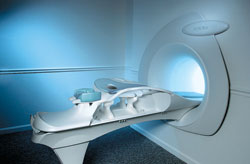
From Aurora Imaging Technology, Inc.;
The Aurora® 1.5T Dedicated Breast MRI System with Bilateral SpiralRODEO™ is the first and only FDA approved MRI device designed specifically for breast imaging. The Aurora System, which is already in clinical use at a growing number of leading breast care centers in the US, Europe, got in December 2006 also the approval from the State Food and Drug Administration of the People's Republic of China (SFDA).
'Some of the proprietary and distinguishing features of the Aurora System include: 1) an ellipsoid magnetic shim that provides coverage of both breasts, the chest wall and bilateral axillary lymph nodes; 2) a precision gradient coil with the high linearity required for high resolution spiral reconstruction;; 3) a patient-handling table that provides patient comfort and procedural utility; 4) a fully integrated Interventional System for MRI guided biopsy and localization; and 5) the user-friendly AuroraCAD™ computer-aided image display system designed to improve the accuracy and efficiency of diagnostic interpretations.'
Device Information and Specification
CONFIGURATION
Short bore compact
TE
From 5 ms for RODEO Plus to over 80 ms, 120 ms for T2 sequences
Around 0.02 sec for a 256x256 image, 12.4 sec for a 512 x 512 x 32 multislice set
20 - 36 cm, max. elliptical 36 x 44 cm
POWER REQUIREMENTS
150A/120V-208Y/3 Phase//60 Hz/5 Wire
| | | | | | | | | | |  Further Reading: Further Reading: | News & More:
|
|
| |
| | | | | |
| |
|
(EPI) Echo planar imaging is one of the early magnetic resonance imaging sequences (also known as Intascan), used in applications like diffusion, perfusion, and functional magnetic resonance imaging. Other sequences acquire one k-space line at each phase encoding step. When the echo planar imaging acquisition strategy is used, the complete image is formed from a single data sample (all k-space lines are measured in one repetition time) of a gradient echo or spin echo sequence (see single shot technique) with an acquisition time of about 20 to 100 ms.
The pulse sequence timing diagram illustrates an echo planar imaging sequence from spin echo type with eight echo train pulses. (See also Pulse Sequence Timing Diagram, for a description of the components.)
In case of a gradient echo based EPI sequence the initial part is very similar to a standard gradient echo sequence. By periodically fast reversing the readout or frequency encoding gradient, a train of echoes is generated.
EPI requires higher performance from the MRI scanner like much larger gradient amplitudes. The scan time is dependent on the spatial resolution required, the strength of the applied gradient fields and the time the machine needs to ramp the gradients.
In EPI, there is water fat shift in the phase encoding direction due to phase accumulations. To minimize water fat shift (WFS) in the phase direction fat suppression and a wide bandwidth (BW) are selected. On a typical EPI sequence, there is virtually no time at all for the flat top of the gradient waveform. The problem is solved by "ramp sampling" through most of the rise and fall time to improve image resolution.
The benefits of the fast imaging time are not without cost. EPI is relatively demanding on the scanner hardware, in particular on gradient strengths, gradient switching times, and receiver bandwidth. In addition, EPI is extremely sensitive to image artifacts and distortions. | | | |
• View the DATABASE results for 'Echo Planar Imaging' (19).
| | |
• View the NEWS results for 'Echo Planar Imaging' (1).
| | | | | | Further Reading: | Basics:
|
|
| |
| | | | | |
| |
|
Quick Overview Please note that there are different common names for this artifact.
DESCRIPTION
Black or bright band
During frequency encoding, fat protons precess slower than water protons in the same slice because of their magnetic shielding. Through the difference in resonance frequency between water and fat, protons at the same location are misregistrated (dislocated) by the Fourier transformation, when converting MRI signals from frequency to spatial domain. This chemical shift misregistration cause accentuation of any fat- water interfaces along the frequency axis and may be mistaken for pathology. Where fat and water are in the same location, this artifact can be seen as a bright or dark band at the edge of the anatomy.
Protons in fat and water molecules are separated by a chemical shift of about 3.5 ppm. The actual shift in Hertz (Hz) depends on the magnetic field strength of the magnet being used. Higher field strength increases the misregistration, while in contrast a higher gradient strength has a positive effect. For a 0.3 T system operating at 12.8 MHz the shift will be 44.8 Hz compared with a 223.6 Hz shift for a 1.5 T system operating at 63.9 MHz.

Image Guidance
| | | |
• View the DATABASE results for 'Chemical Shift Artifact' (7).
| | | | | | Further Reading: | | Basics:
|
|
News & More:
| |
| |
| | | | | |
| |
|
(FAT SAT) A specialized technique that selectively saturates fat protons prior to acquiring data as in standard sequences, so that they produce a negligible signal. The presaturation pulse is applied prior to each slice selection. This technique requires a very homogeneous magnetic field and very precise frequency calibration.
Fat saturation does not work well on inhomogeneous volumes of tissue due to a change in the precessional frequencies as the difference in volume affects the magnetic field homogeneity. The addition of a water bag simulates a more homogeneous volume of tissue, thus improving the fat saturation. Since the protons in the water bag are in motion due to recent motion of the bag, phase ghosts can be visualized.
Fat saturation can also be difficult in a region of metallic prosthesis. This is caused by an alteration in the local magnetic field resulting in a change to the precessional frequencies, rendering the chemical saturation pulses ineffective.
See also Fat Suppression, and Dixon. | | | | | |
• View the DATABASE results for 'Fat Saturation' (9).
| | | | | | Further Reading: | | Basics:
|
|
News & More:
| |
| |
| | | | | |
| |
|
( STIR) Also called Short Tau ( t) ( inversion time) Inversion Recovery. STIR is a fat suppression technique with an inversion time t = T1 ln2 where the signal of fat is zero ( T1 is the spin lattice relaxation time of the component that should be suppressed). To distinguish two tissue components with this technique, the T1 values must be different. Fluid Attenuation Inversion Recovery ( FLAIR) is a similar technique to suppress water.
Inversion recovery doubles the distance spins will recover, allowing more time for T1 differences. A 180° preparation pulse inverts the net magnetization to the negative longitudinal magnetization prior to the 90° excitation pulse.
This specialized application of the inversion recovery sequence set the inversion time ( t) of the sequence at 0.69 times the T1 of fat. The T1 of fat at 1.5 Tesla is approximately 250 with a null point of 170 ms while at 0.5 Tesla its 215 with a 148 ms null point. At the moment of excitation, about 120 to 170 ms after the 180° inversion pulse (depending of the magnetic field) the magnetization of the fat signal has just risen to zero from its original, negative, value and no fat signal is available to be flipped into the transverse plane.
When deciding on the optimal T1 time, factors to be considered include not only the main field strength, but also the tissue to be suppressed and the anatomy. In comparison to a conventional spin echo where tissues with a short T1 are bright due to faster recovery, fat signal is reversed or darkened.
Because body fluids have both a long T1 and a long T2, it is evident that STIR offers the possibility of extremely sensitive detection of body fluid. This is of course, only true for stationary fluid such as edema, as the MRI signal of flowing fluids is governed by other factors.
See also Fat Suppression and Inversion Recovery Sequence. | | | | | |
• View the DATABASE results for 'Short T1 Inversion Recovery' (3).
| | | | | | Further Reading: | Basics:
|
|
News & More:
| |
| |
| | | | |
| | | |
|
| |
 | Look
Ups |
| |


